The different types of lightning protection systems
Thunderstorms are natural phenomena that pose a huge danger to buildings and people. The lightning conductor is a lightning protection device whose role is to capture direct lightning strikes in a defined area. The lightning current captured is carried to earth by conductive materials and dissipated in a dedicated earthing system. By channelling these electrical discharges (whose intensity varies usually between 1 kA and 200 kA). Recently, on Tuesday 12 November 2024, a lightning discharge was recorded near the castelet circuit with an intensity in excess of 350 kA!
Lightning protection systems prevent the risk of structural damage and fire. There are several different technologies, and it is important to know how to distinguish between them so you can choose the one best suited to your building.
Conventional systems (standard NF EN 62-305)
The Franklin rod
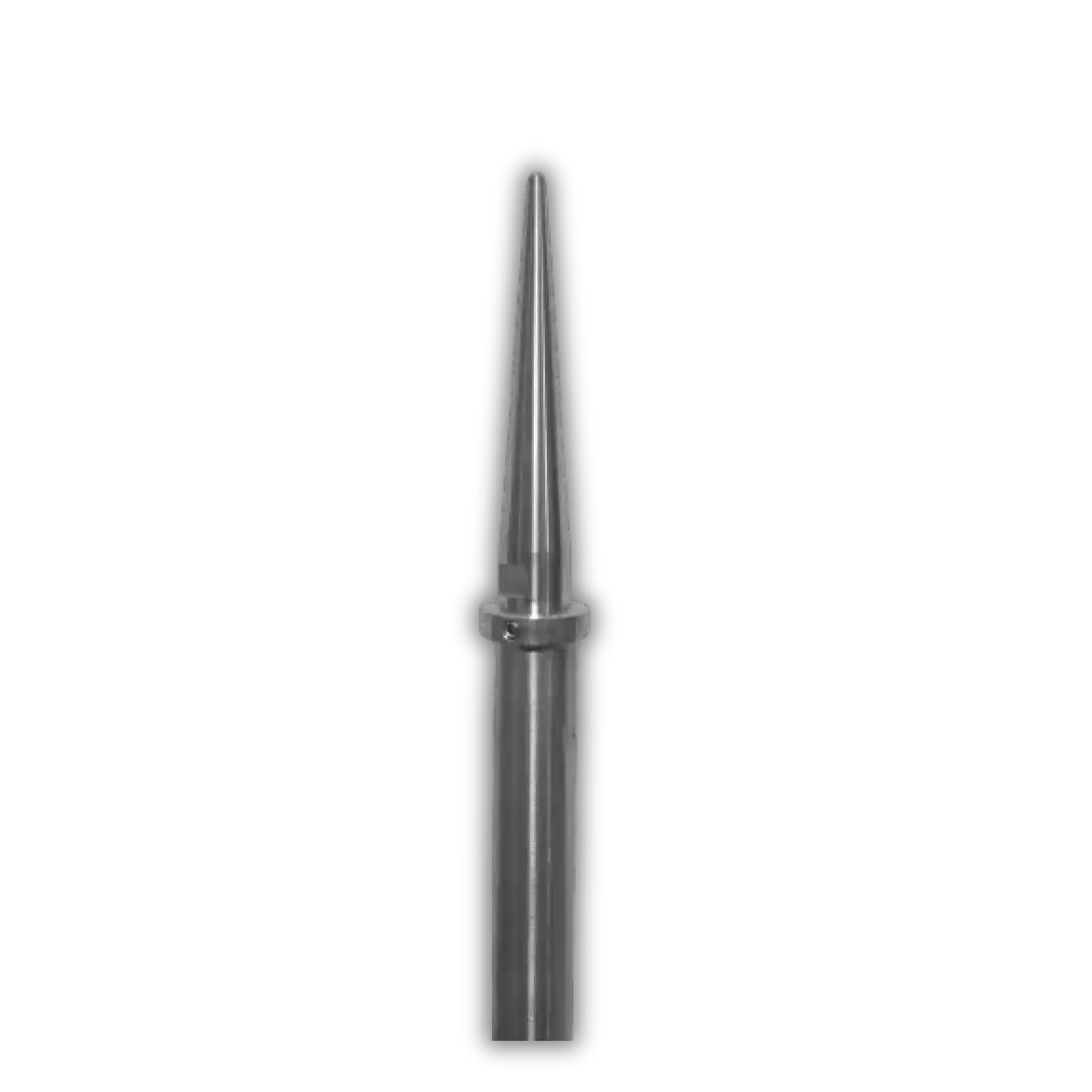
The Franklin rod is the oldest and best-known technology, historically invented by the Frenchman Jacques de Romas (1713-1776) and Benjamin Franklin (1706 – 1790). It consists of a metal rod installed at the highest point of the building to be protected, and connected to earthing point(s) by down conductor(s). In the most favourable case, the maximum protection radius of this system is 30 m (risk level = IV; height = 60 m).
Advantages of the Franklin rod:
- Easy to install
- Financially attractive for small-scale projects
- Can be discreetly integrated into certain structures
Disadvantages of the Franklin rod:
- Limited protection radius
- The larger the project, the less attractive the technology is financially.
- Mechanical strength of masts constraint
Example of structures suitable for this system:
- Antennas and pylons
- Individual houses
- Small churches and monuments
- Chimney tops
Related standards:
- Components: IEC EN 62561 – Part 1 to 8
- Installation: IEC EN 62305-3
The meshed cage
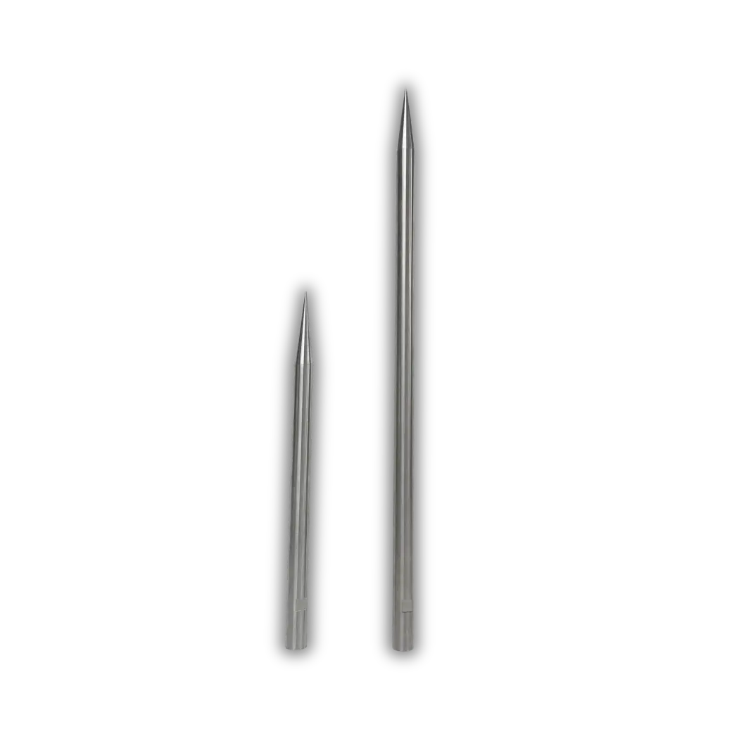
Derived from the Faraday cage, meshed cage protection is a protection method that consists of encircling a building with a mesh of conductive materials installed on the roof and facade. An earth loop (type B) is also installed around the building to dissipate the lightning current efficiently. In addition, lightning rods are placed on the roof and on high points. The mesh size varies between 5 and 20 m depending on the level of protection required: the higher the level required, the smaller the mesh size.
Advantages of the meshed cage:
- Reduction of the effects of electromagnetic radiation inside the protected structure
- Contributes to overall equipotentiality between conductive structures and earth
Disadvantages of the meshed cage:
- Complex installation: lots of materials to install on the building and in the ground
- Protection method very costly in terms of materials and labour
Example of structures suitable for this system:
- Data Centres
- Scanners
Related standards:
- Components: IEC EN 62561 – Part 1 to 8
- Installation: IEC EN 62305-3
Taut wire lightning conductors
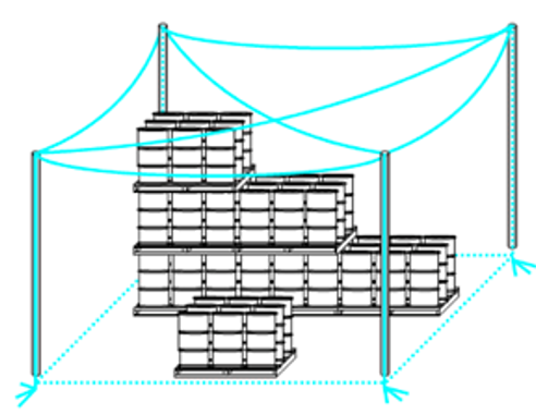
The protection principle is identical to that of the meshed cage, except that the conductors are installed at a distance from the structure to be protected. This distance isolates the building from the lightning current by keeping them apart. The tensioned wires (made of the conductive materials specified in standard IEC EN 62305-3) are connected to down conductors linked to an earthing system. The size of the mesh and the distance between the down conductors are determined using the fictitious sphere or protection angle method.
Advantages of the taut wire lightning conductors:
- Reduction of the effects of electromagnetic radiation inside the protected structure
- Contributes to overall equipotentiality between conductive structures and earth
- Protection of open areas
Disadvantages of the taut wire lightning conductors:
- Complex installation: lots of materials to install on the building and in the ground
- Protection method very costly in terms of materials and labour
- Protection solution that is not very discreet or aesthetically pleasing
- Taut wires pose logistical and safety problems in certain areas (e.g. movement of handling equipment).
Example of structures suitable for this system:
- Outdoor storage areas
- Data Centres
- Scanners
- Rocket launch pad (see Ariane rocket in our references)
Related standards
- Components: IEC EN 62561 – Part 1 to 8
- Installation: IEC EN 62305-3
Modern systems (NF C 17-102)
The Early Streamer Emission air terminal (ESEat)
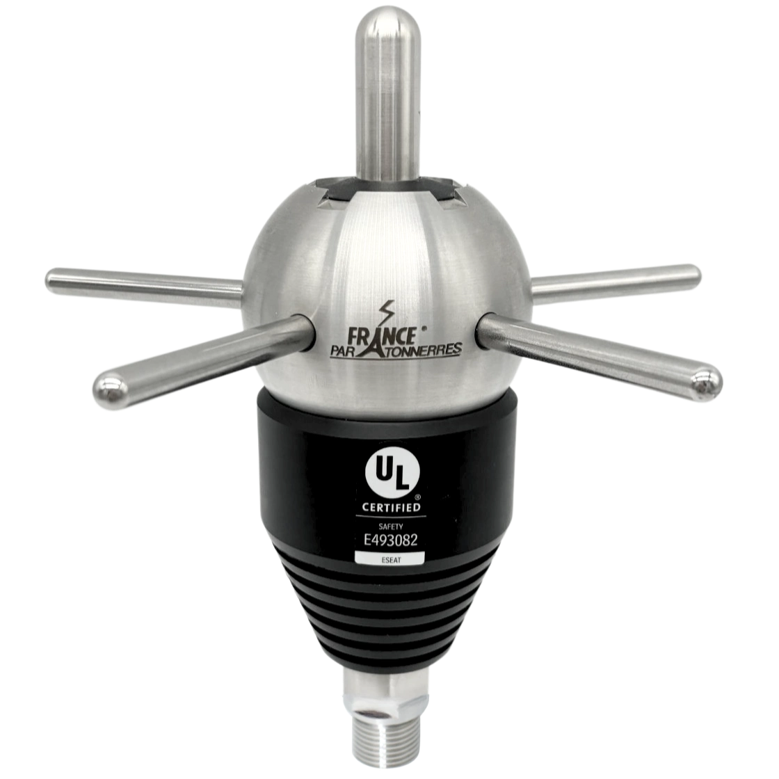
This French technology, which appeared in the 1980s, is the result of long development work involving institutions such as the CNRS. The principle of the Early Streamer Emission (ESE) air terminal is to artificially generate, by means of an ionisation system, an ascending electrical tracer that occurs before the ‘natural’ electrical tracers. The time difference between the electrical initiation (generation of the tracer) of a Franklin rod and that of a ESEat is referred to as the initiation advance. This advance, measured in laboratories and in situ, is between 10 µs and 60 µs depending on the model.
The aim of a ESEat, and therefore the advantage of the ignition advance, is to create a privileged point of impact for the lightning current in order to capture it at a higher level. By capturing the lightning at a greater height, a larger area can be covered.
Different manufacturers use different processes to generate the electrical tracer. Two technical solutions are available on the market: the electronically triggered ESEat and the geometrically triggered ESEat:
- Electronically triggered ESEat : These products are equipped with an electronic device responsible for ionising the air around their tip to facilitate the attraction of lightning by creating a conductive path between the cloud and the ground. This electronic device is powered either by a battery or by elements that capture the energy generated by the ambient electric field as a storm approaches.
- Geometrically triggered ESEat : This type of product is designed to raise its electrical potential very quickly just before the lightning strikes. As soon as the potential has reached the air ionisation voltage, sparks are produced at a spark gap to produce the upward tracer. Among the market leaders, our IONIFLASH MACH NG range uses this technique, which has the advantage of being longer-lasting and requiring less maintenance.
Advantages of the Early Streamer Emission air terminal:
- Easy to install
- Greater protection radius
- Financially attractive for large-scale projects
- Protection of open areas
- Integrates discreetly into structures
Disadvantages of the Early Streamer Emission air terminal:
- The smaller the project, the less attractive the technology is financially.
- Mechanical strength of masts constraint
- Constraint of earth connection with resistivity less than 10 Ohms
Example of structures suitable for this system:
- Industrial plant
- Storage facilities
- Solar fields
- Hazardous areas
- Large buildings / monuments
Related standards:
- Components: NF C 17-102 (or equivalent) / IEC EN 62561 – Parts 1 to 8
- Installation: NF C 17-102 (or equivalent)
France Paratonnerres’ products
Our company, which specialises in the design and production of high-range lightning protection solutions, is able to respond to all requests relating to the technologies presented in this article. Whether your need is for a project study, the supply of equipment, installation or inspection, our partner network will be able to meet it.

