How to install an ESE air terminal?
Installing an ESE air terminal (ESE for Early Streamer Emission) enables a building (or an area) to be protected from direct effects of lightning. For this protection to be effective, you need to install a complete lightning protection system that complies with standards NF C 17-102 : 2011 (or equivalent in your country). The following guide is based mainly on the French standard NF C 17-102: 2011. In addition to this standard, each country adds its own specific regulations, which we will not go into here. Follow our advice to install an ESE air terminal in full compliance.
The installation of a Lightning Protection System (LPS) can be split into 8 parts:
Early Streamer Emission Air Terminal (ESEAT)
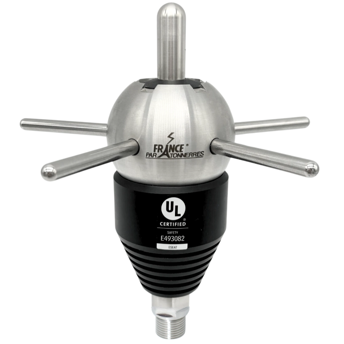
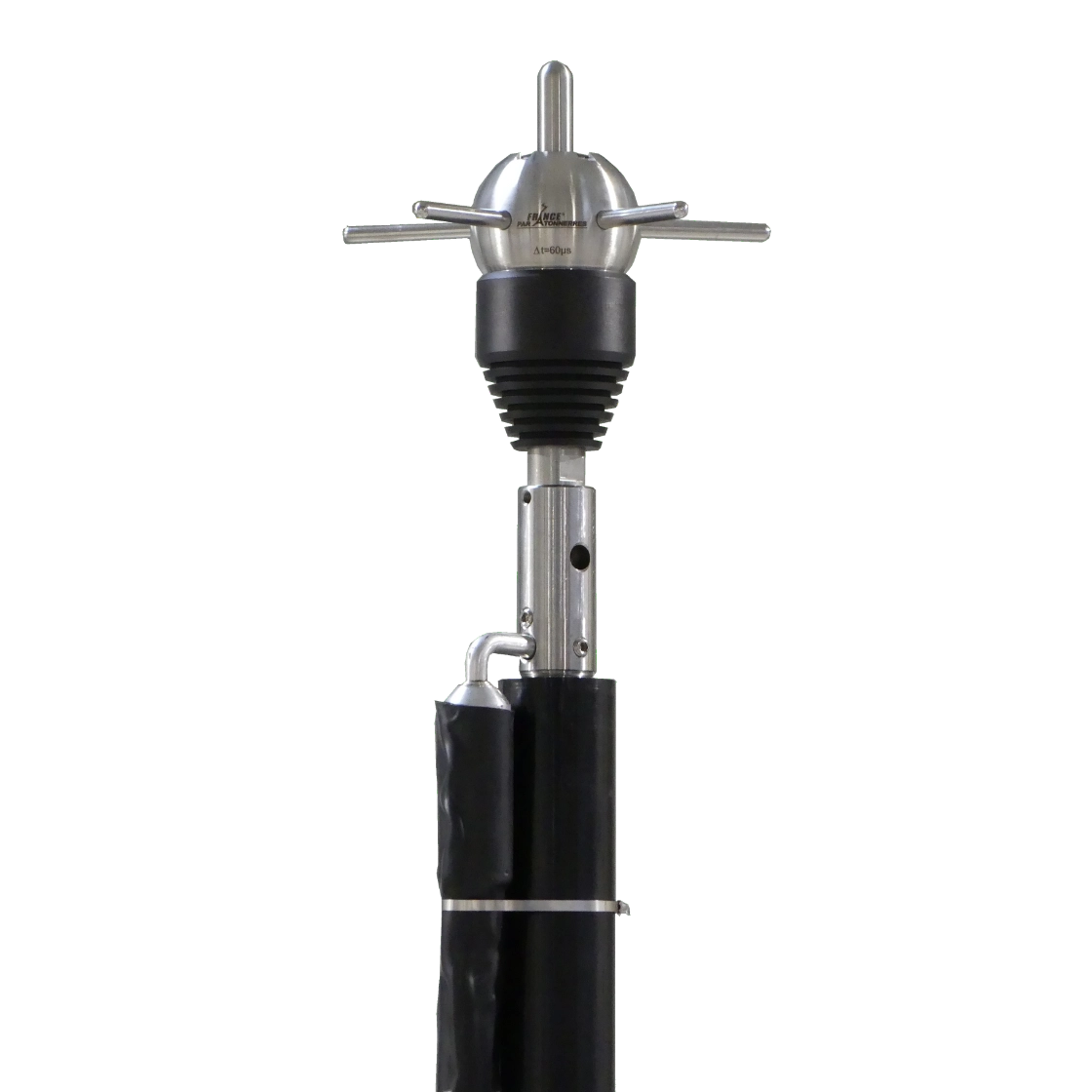
The role of an ESE air terminal (ESEAT) is to capture lightning strikes in a given area. For this to be possible, the ESEAT must be positioned as the highest point of the area to be protected and be connected to the ground. The air terminal should be installed at least 2m above any element, it is often considered to increase its height to catch the lightning higher up and cover a larger area.
To be able to install an ESEAT effectively, you absolutely must know the level of protection required to protect the site in question. To do this, you can contact our design office or use our software IONEXPERT 4000.
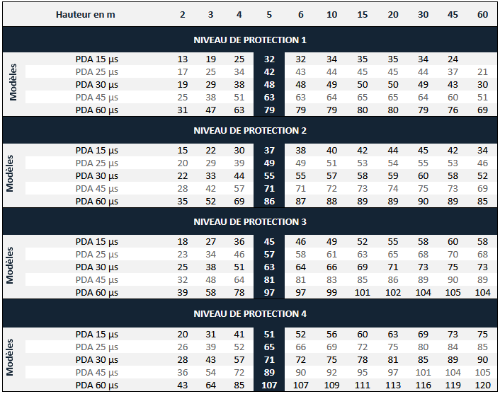
Once the level of protection has been determined, the following table can be used to select the ESE air terminal to be used (standard NF C 17-102:2011):
Height in m | 2 | 3 | 4 | 5 | 6 | 10 | 15 | 20 | 30 | 45 | 60 | |
LEVEL OF PROTECTION 1 | ||||||||||||
Product | ESEAT 15 µs | 13 | 19 | 25 | 32 | 32 | 34 | 35 | 35 | 34 | 24 |
|
ESEAT 25 µs | 17 | 25 | 34 | 42 | 43 | 44 | 45 | 45 | 44 | 37 | 21 | |
ESEAT 30 µs | 19 | 29 | 38 | 48 | 48 | 49 | 50 | 50 | 49 | 43 | 30 | |
ESEAT 45 µs | 25 | 38 | 51 | 63 | 63 | 64 | 65 | 65 | 64 | 60 | 51 | |
ESEAT 60 µs | 31 | 47 | 63 | 79 | 79 | 79 | 80 | 80 | 79 | 76 | 69 | |
LEVEL OF PROTECTION 2 | ||||||||||||
Product | ESEAT 15 µs | 15 | 22 | 30 | 37 | 38 | 40 | 42 | 44 | 45 | 42 | 34 |
ESEAT 25 µs | 20 | 29 | 39 | 49 | 49 | 51 | 53 | 54 | 55 | 53 | 46 | |
ESEAT 30 µs | 22 | 33 | 44 | 55 | 55 | 57 | 58 | 59 | 60 | 58 | 52 | |
ESEAT 45 µs | 28 | 42 | 57 | 71 | 71 | 72 | 73 | 74 | 75 | 73 | 69 | |
ESEAT 60 µs | 35 | 52 | 69 | 86 | 87 | 88 | 89 | 89 | 90 | 89 | 85 | |
LEVEL OF PROTECTION 3 | ||||||||||||
Product | ESEAT 15 µs | 18 | 27 | 36 | 45 | 46 | 49 | 52 | 55 | 58 | 60 | 58 |
ESEAT 25 µs | 23 | 34 | 46 | 57 | 58 | 61 | 63 | 65 | 68 | 70 | 68 | |
ESEAT 30 µs | 25 | 38 | 51 | 63 | 64 | 66 | 69 | 71 | 73 | 75 | 73 | |
ESEAT 45 µs | 32 | 48 | 64 | 81 | 81 | 83 | 85 | 86 | 89 | 90 | 89 | |
ESEAT 60 µs | 39 | 58 | 78 | 97 | 97 | 99 | 101 | 102 | 104 | 105 | 104 | |
LEVEL OF PROTECTION 4 | ||||||||||||
Product | ESEAT 15 µs | 20 | 31 | 41 | 51 | 52 | 56 | 60 | 63 | 69 | 73 | 75 |
ESEAT 25 µs | 26 | 39 | 52 | 65 | 66 | 69 | 72 | 75 | 80 | 84 | 85 | |
ESEAT 30 µs | 28 | 43 | 57 | 71 | 72 | 75 | 78 | 81 | 85 | 89 | 90 | |
ESEAT 45 µs | 36 | 54 | 72 | 89 | 90 | 92 | 95 | 97 | 101 | 104 | 105 | |
ESEAT 60 µs | 43 | 64 | 85 | 107 | 107 | 109 | 111 | 113 | 116 | 119 | 120 | |
Standard NF C 17-102 of 2011 requires that the ESEAT installed be testable. In practice, it is advisable to choose a model that can be tested remotely to facilitate the test procedure and avoid non-compliance on the part of the inspection authorities.
Fixing of the ESE Air Terminal
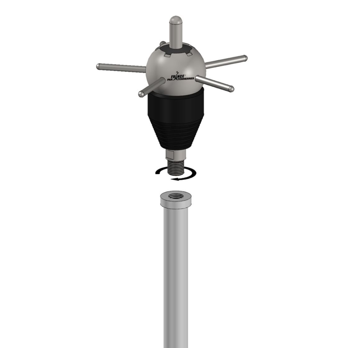
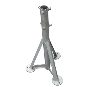
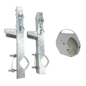
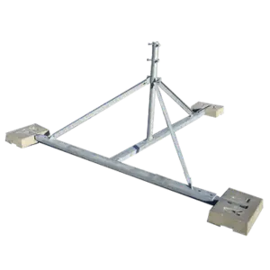
The ESEAT should be fixed on a pole that allows it to reach the height required to protect the defined area. To reach a height of 5m, which is the optimum height (protection radius/cost ratio), extension masts can be used to extend the attachment pole. However, if the overall height exceeds 6m, we strongly advise you to use a guy wire kit.
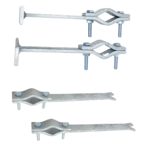
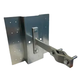
This set of pole + extension masts must then be securely attached to the structure to be protected. There are several ways of doing this:
Down conductors
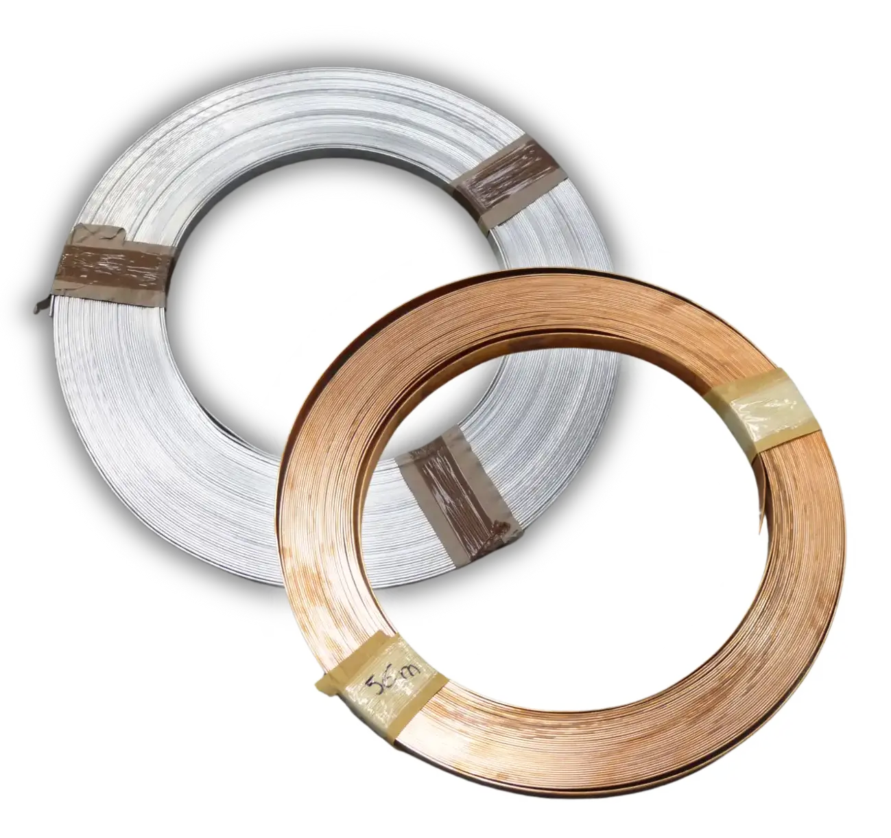
The lightning current catched by the ESEAT must be conducted to the ground to be dissipated. To achieve this, standard NF C 17-102 : 2011 requires each ESE air terminal to be connected to the ground by at least two down conductors. These conductors can be specific (see below table) or, in some cases, take all or part of the natural components already present on the structure. The upper base of the conductor must be connected directly under the air terminal’s head or to the bottom of the fixing system.
List of materials that can be used as down conductors (standard IEC EN 62305-2):
| Material | Type | Cross-sectional area mm 2 |
|---|---|---|
| Copper Tinplated copper | Solid tape | 50 |
| Solid round b | 50 | |
| Stranded b | 50 | |
| Solid round c | 176 | |
| Aluminum | Solid tape | 70 |
| Solid round | 50 | |
| Stranded | 50 | |
| Aluminum alloy | Solid tape | 50 |
| Solid round | 50 | |
| Stranded | 50 | |
| Solid round c | 176 | |
| Copper coated aluminum alloy | Solid round | 50 |
| Stainless steel | Solid tape d | 50 |
| Solid round d | 50 | |
| Stranded | 70 | |
| Solid round c | 176 | |
|
a Mechanical and electrical characteristics, as well as corrosion resistance properties, must meet the requirements of the future EN 50164 series. b 50 mm2 (8 mm diameter) may be reduced to 25 mm2 in certain applications where mechanical strength is not an essential requirement. In such cases, consideration should be given to reducing the spacing between fasteners. c Applicable to rods and guided earth electrodes. For rods where mechanical stress such as wind load is not critical, a 9.5 mm diameter rod 1 m long can be used. d If thermal and mechanical considerations are important, then these values should be increased to 75 mm2. | ||
Down conductors should always be routed as directly as possible, preferably outside the building. They should be installed as straight as possible, with curves as rounded as possible (see diagram below).

Down conductors should also be kept as spaced apart as possible, if possible on opposite walls. When two conductors are on the same wall, they should be at least 10m apart.
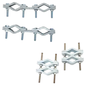
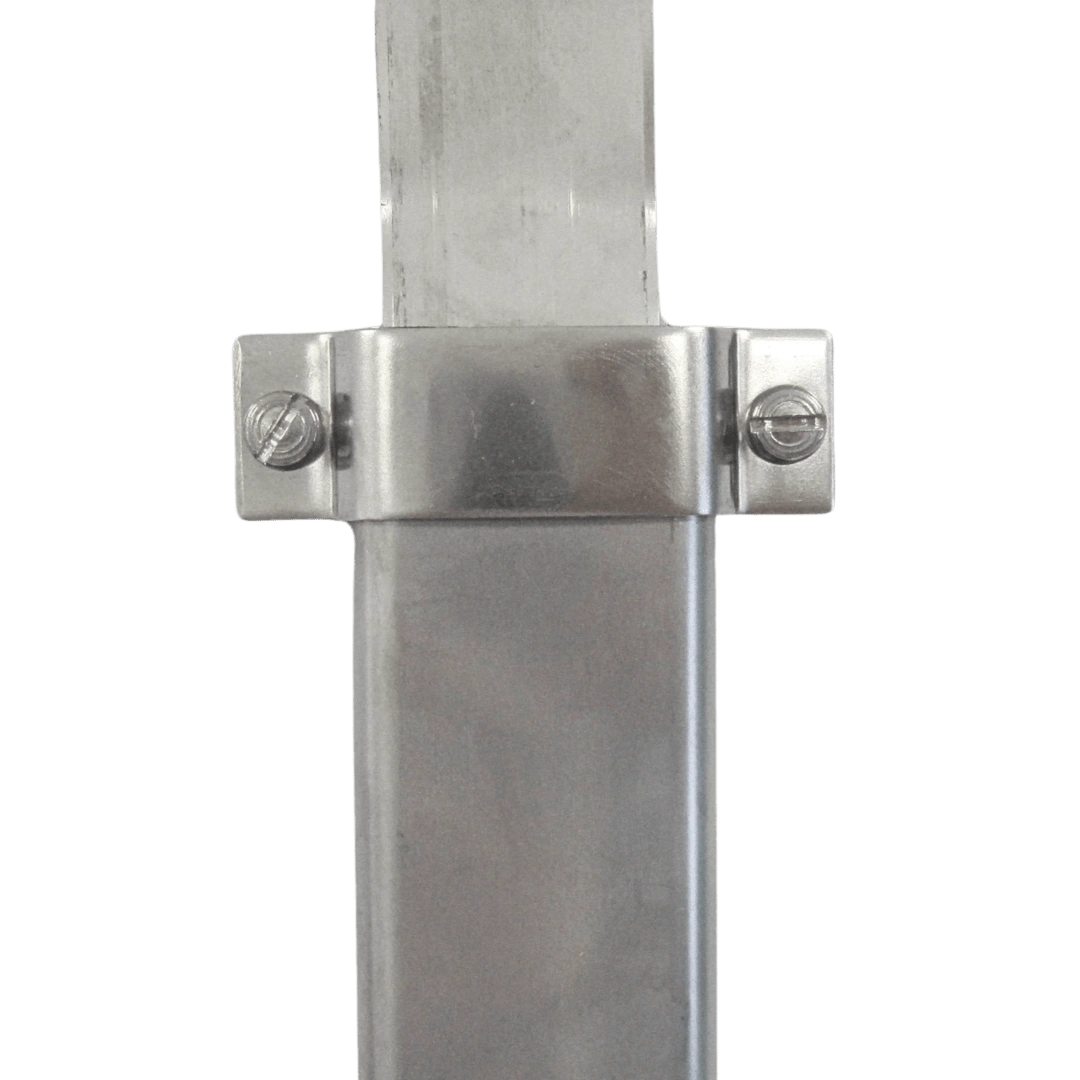
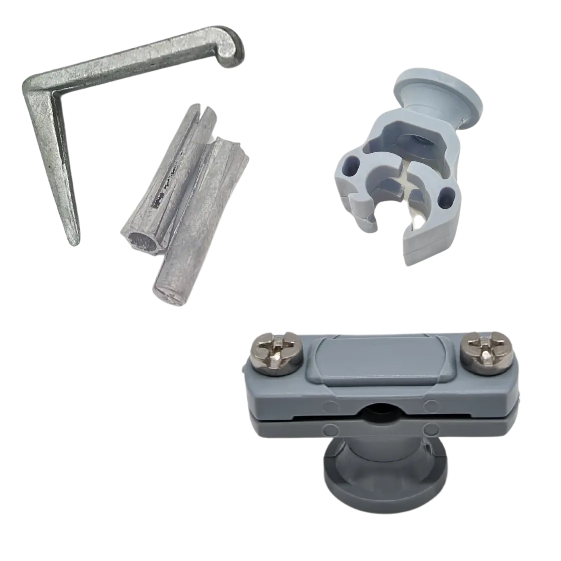
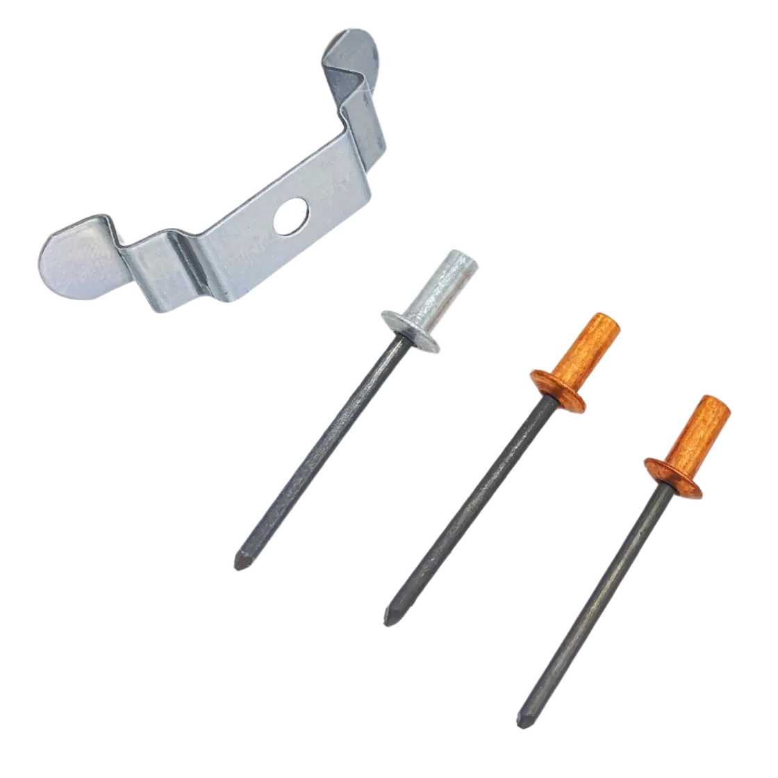
Conductors must be fixed to the structure to be protected at a rate of 3 fasteners per meter (i.e. 1 fastener every 33 cm). It is important to choose fasteners that are suitable for the support and the conductive material. The following accessories can be used:
Wall
Metal cladding
Roof tiles
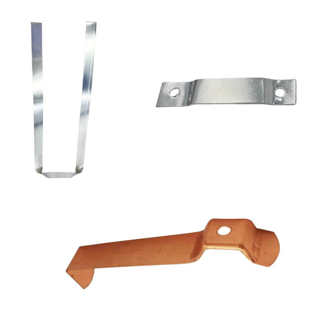
Flat roof
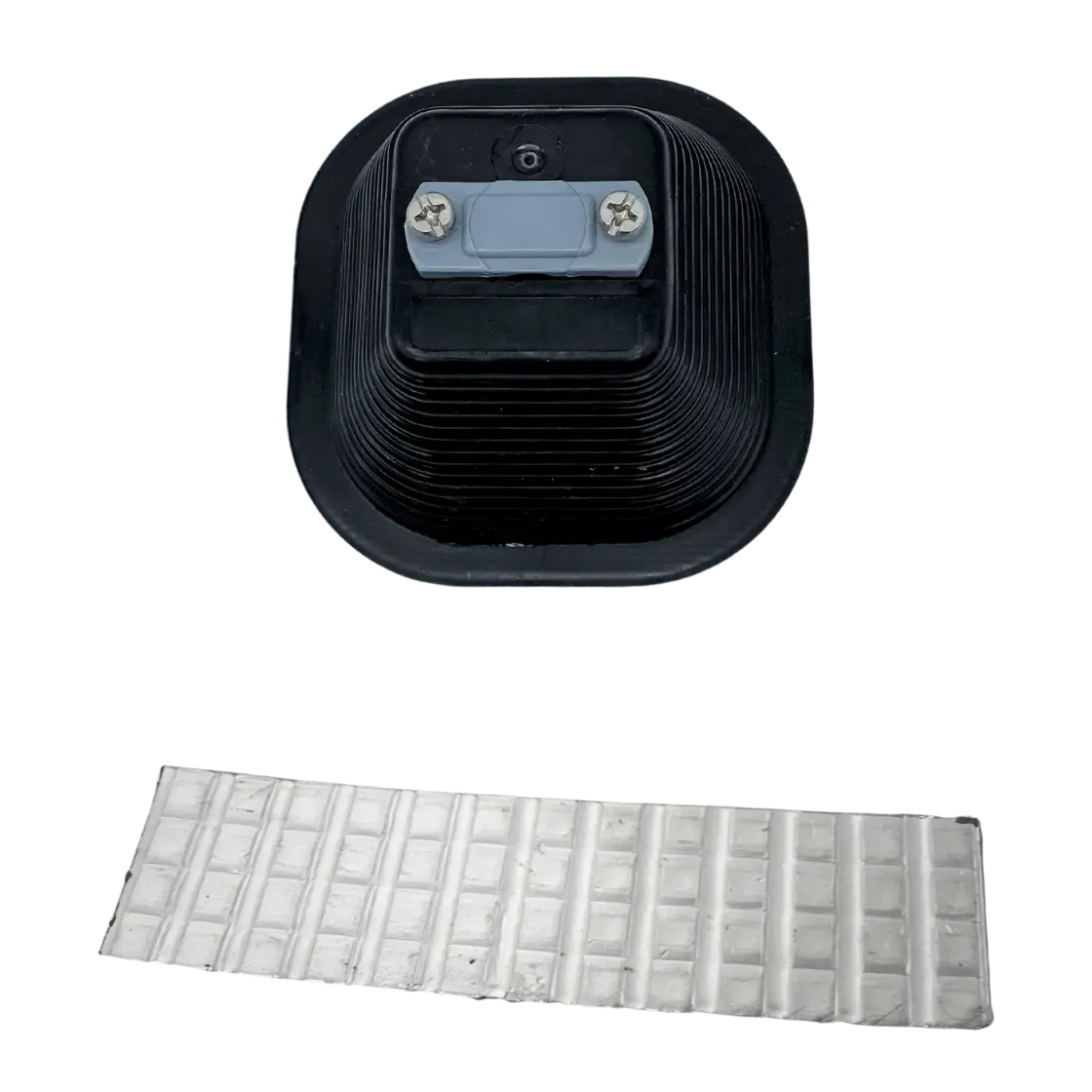
Roof ridge
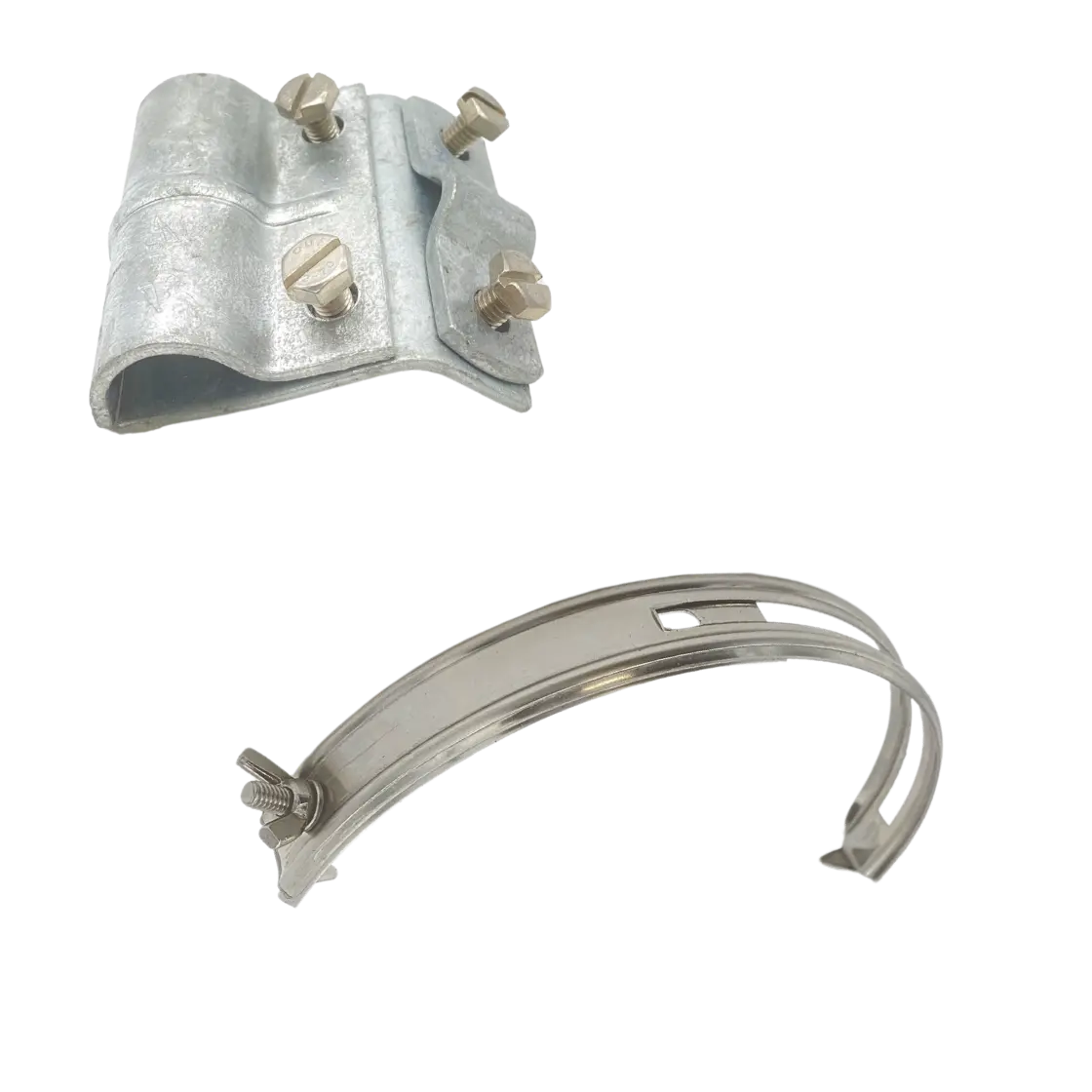
Down conductors must be connected together using connectors specifically designed for this purpose and of the same type as the conductor. Down conductors must never be pierced.
Specific cases:
- If an ESEAT is installed on an insulated structure (as defined in the standard), a single conductor may be sufficient.
- If a site is protected by several ESE air terminals, the down conductors can be shared. However, the number of conductors must be at least equal to the number of ESEAT.
Down conductors bottom
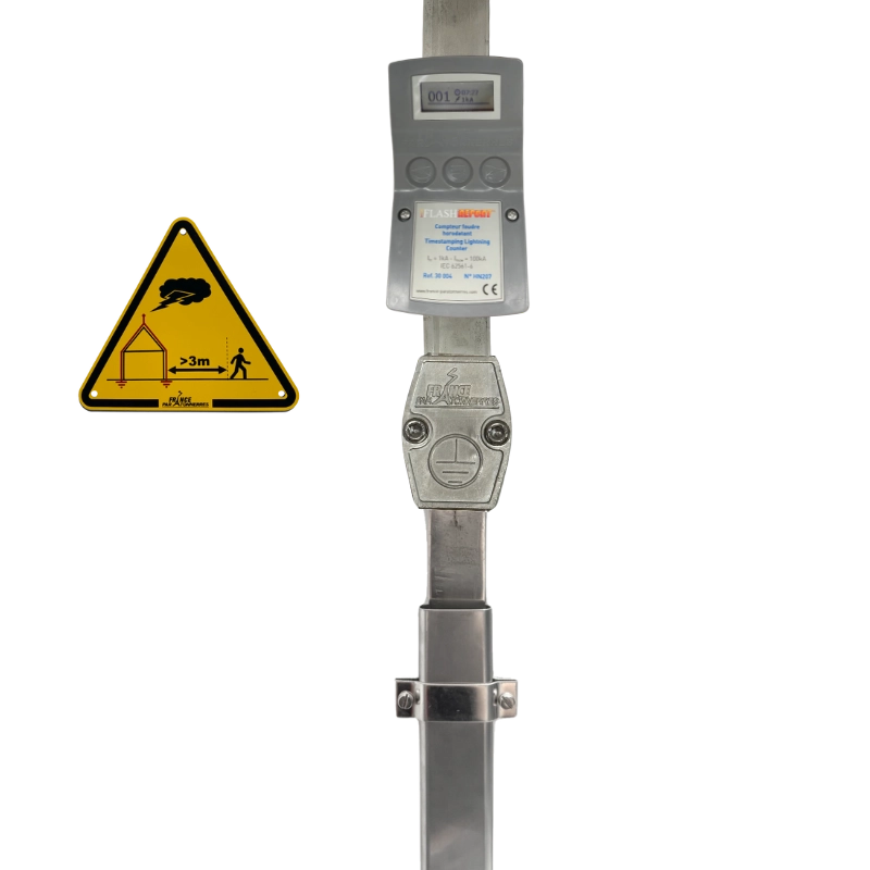
The down conductor bottom is the part of the down conductor that is at ground level. Several essential components must be present:
Protective sleeve
The bottom of each down conductor must be protected against physical damages over a height of at least 2 m by means of a metal protective sleeve to prevent any breakage of the conductor. We recommend that you bury the sleeve slightly (5 cm) so that there is no gap between the ground and the sleeve.
Inspection joint (or disconnect terminal)
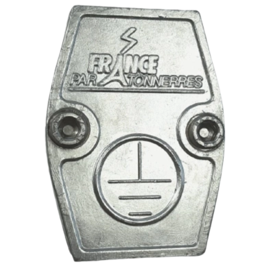
Each down conductor must be able to be disconnected to take earth measurements independently of the rest of the system. An inspection joint must therefore be installed above the protective sleeve to enable this disconnection to be made easily.
Warning plate
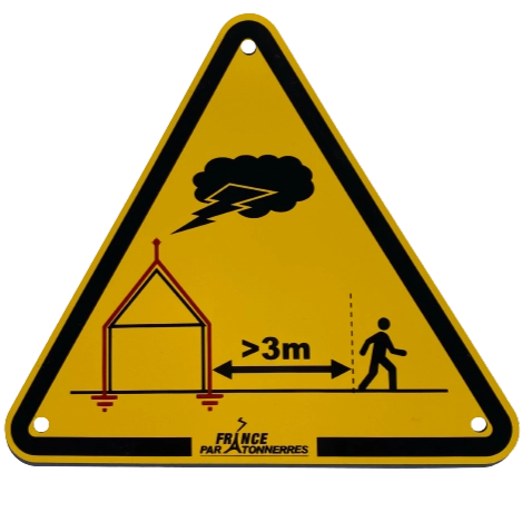
It is also required to install a sign to warn of the danger of being near the installation in the event of a storm. One warning sign per down conductor should be installed at man-height.
Lightning strikes counter
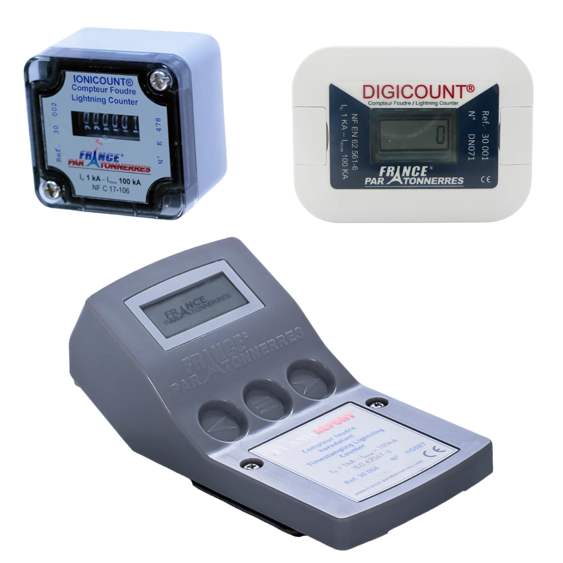
A lightning strikes counter is a device used to record storm activity in the installation by counting the number of strikes suffered by the ESEAT. This counter can be installed on the down conductor at the insecption joint level. The presence of a lightning strike counter can trigger an inspection and maintenance process in the event of an impact on the lightning conductor.
Lightning earthing systems
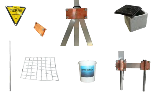
Installing an ESE air terminal allows lightning strikes to be catched, but a system must also be put in place to dissipate the current into the ground. To do this, each ESEAT must be connected to an earthing system using down conductors. To facilitate the evacuation of the lightning current, the resistance of the earthing points must be as low as possible, and always less than 10Ω. This is often the aspect feared by installers, as it is often difficult to estimate at the time of costing whether the resistance of the earth will be easy to lower or not at the time of construction. We recommend measuring the resistivity of the earth before calculating the cost of an installation.
Type A (or “crow’s foot”) earthing system
In this case, an earthing system must be made for each down conductor. Type A earth connections must all have a resistance of less than 10 Ω and comprise at least two electrodes.
Where it is impossible to achieve a resistance of less than 10 Ω, the total length of buried electrodes should be at least 160m horizontal and 80m vertical for protection level I and at least 100m horizontal and 50m vertical for other protection levels (the length of vertical electrodes is equal to 2). The use of earthing grids (62561-2 compliant) is the best solution here.
Conductors must be buried at a minimum depth of 50 cm.

Type B earthing system (or “loop earthing”)
A Type B earthing system, known as a “loop earth”, is made up of a loop outside the structure over a length of at least 80%, i.e. an earth connection at the bottom of the pit.
The conductors must have a minimum cross-section of 50mm². In addition, in line with each down conductor, at least one 4m horizontal electrode or one 2m vertical electrode must be connected to earth in a loop.
Equipotential bonding
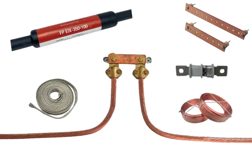
When installing a lightning conductor, one aspect is all too often neglected: the installation of equipotential bonding. These connections prevent electrical arcing between down conductors and parts of the structure to be protected.
Earthing systems equipotential bonding
All lightning earthing systems and electrical earthing systems must be interconnected using conductive links. It is usual to install 25 mm² copper cable.
Separation distances
Lightning protection regulations agree on the principle of a separation distance s to be respected to ensure the electrical insulation of elements present in the vicinity of the Lightning Protection System (LPS). The distance d between the SPF and the element to be insulated must be greater than s:
s = ki * (kc / km) * L
The ki coefficient is directly linked to the level of lightning protection to be applied:
- Level I = 0.08
- Level II = 0.06
- Level III = 0.04
- Level IV = 0.04
The coefficient kc corresponds to the number of down conductors:
- 1 down conductor = 1
- 2 down conductor = 0,75 (if type A earthing)
- 3 down conductor = 0,60 (if type A earthing)
- 4 down conductor or more = 0,41 (if type A earthing)
The coefficient km is linked to the separating material:
- Air = 1
- Concrete / Brick = 0,5
The coefficient L (in metres) corresponds to the length between the starting point of the separation distance s and the nearest equipotential bonding point.
When technical constraints make it impossible to respect the separation distance calculated above, it is then necessary to balance the potentials by creating links. These connections between the LPS and the surrounding elements must be as direct and straight as possible. We recommend using a 50 mm² conductor capable of withstanding the lightning current.
For equipotential bonding of sensitive elements (electrical cabinets, aerial masts, satellite dishes, etc.), we recommend installing an equipotential spark gap. This solution ensures potential balancing and the flow of static charges, while at the same time insulating the equipment during normal operation.
Surge Protection Devices (SPD)
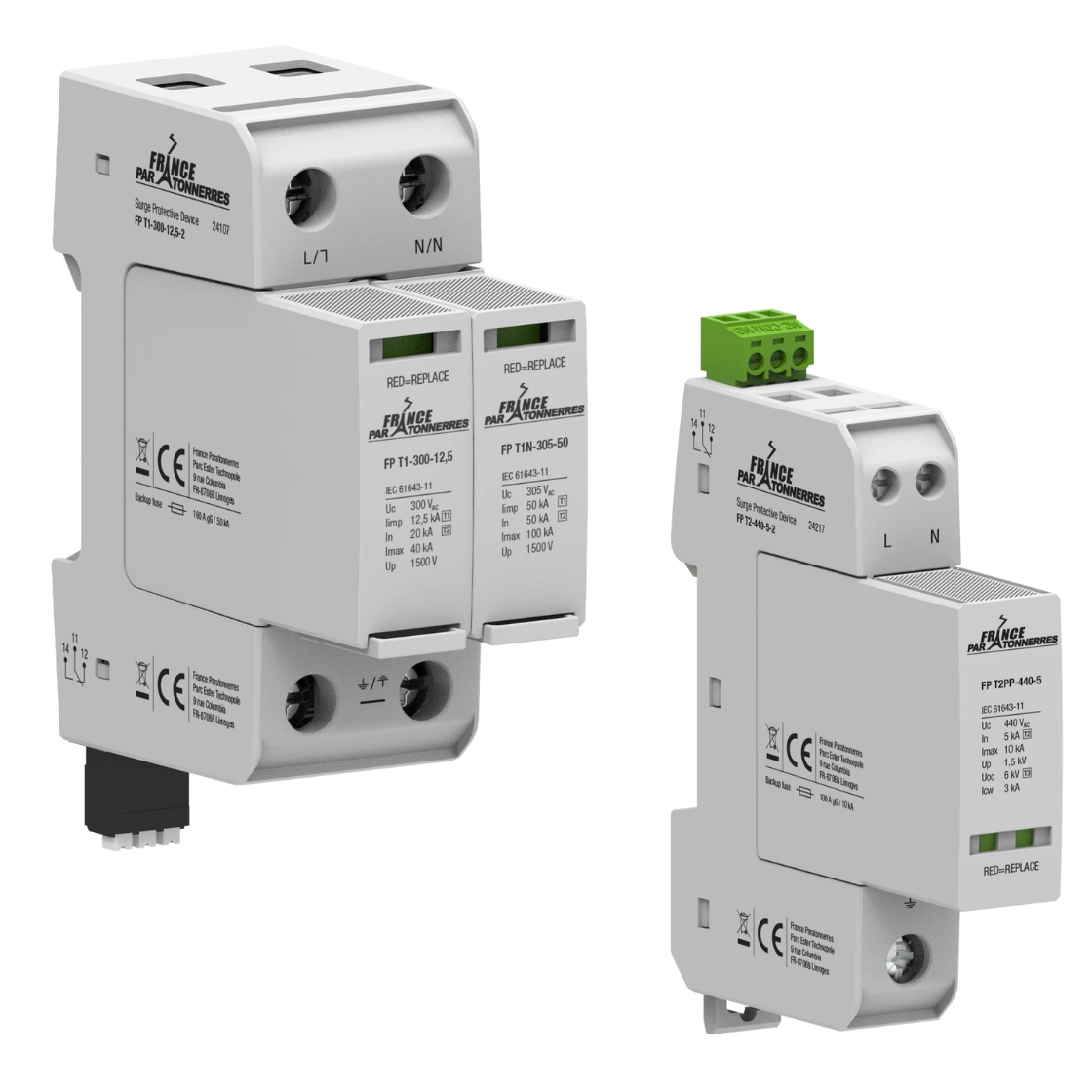
In addition to installing an external lightning protection system (ESEAT), internal lightning protection (SPD) is mandatory (depending on countries regulations). Even if your reference regulations do not require you to install SPDs, we strongly recommend that you do so.
There are several types of lightning arrester:
- Type 1 SPDs
- Type 2 SPDs
- Type 3 SPDs
- Telephon SPDs
- Photovoltaic SPDs
- Etc…
Isolated Lightning Protection System
One of the new trends in lightning protection is the use of isolated conductors to connect a ESE air terminal to an earthing system. This solution reduces the separation distances between the LPS and nearby elements.
Be careful not all isolated conductors offer the same performance, and France Paratonnerres’ FPIC® conductor holds the record for reducing the distance s by 95 cm!

The second advantage of the insulated conductor is that its use allows the Lightning Protection System to be considered insulated (in compliance with the conditions of IEC TS 62561-8 and NF C 17-102). And in some cases, having an isolated lightning protection system means you can connect a ESE air terminal to just one earthing system.
The insulated conductor is an innovative solution that greatly reduces installation costs. However, there are certain conditions to be met for an LPS to be considered insulated:
- Maximum lengths
Taking into account the equivalent separation distance of the insulated cable (95 cm for FPIC® France Paratonnerres) and according to the calculations in standard NF C 17-102: 2011, maximum lengths must not be exceeded:
| No. of FPIC® / ESEAT | Level I | Level II | Level III+IV |
| 1 | 11.90 m | 15.80 m | 23.80 m |
| 2 | 15.80 m | 21.10 m | 31.70 m |
| 3 | 19.80 m | 26.40 m | 39.60 m |
- Components to be used
In addition to the isolated conductor, accessories must be used to isolate the complete Lightning Protection System. They must comply with current standards.

